Start creating a new drawing and this case create an empty sheet. Normally when starting a new drawing you will only have one sheet and no views.
Catia V5 Tip How To Create A Drawing View From A Scene Rand 3d Insights From Within
Go back to the scene and select one of the elements on it 5.
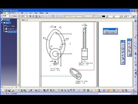
. Learn the definition of isometric view and then discover how to draw objects using isometric view through examples. In the Drawing window click Isometric View in the Views toolbar Projections sub-toolbar. Isometric view is a type of alignment that gives drawn objects their depth.
After that you have the 3D Colors option. Right-click the view and select Isometric view object Modify Projection plane. Again generate an.
For example in the widely used original PSVT-R test 5 the isometric drawings in 7. Create an isometric view of the part. Click the 3D part.
In the Drawing window click Isometric View in the Views toolbar Projections sub-toolbar. Tile your windows vertically to visualize the 3D part and the sheet at the same time. 95 CATIA drawing Tutorial.
Right-click the isometric view and select Properties. Some of the edges are not projected. Changing the View Properties.
Create a new Drawing file. Click the Drawing window and click the Isometric View icon from the Views toolbar Projections subtoolbar. For more CATIA Tutorials.
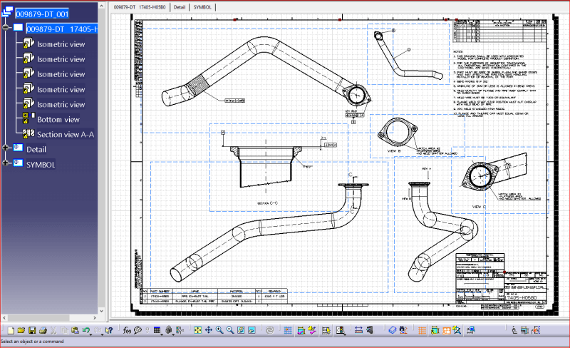
A Each sheet created in a drawing is represented in the specification tree. To produce an isometric projection it is necessary to place the object so that its principal edges make equal angles with the plane of projection and are therefore foreshortened equally. I guess you want it on a drawing.
Create a new drawing view to which the breakout view will be applied. On the View tab check 3D Colors in the Dress-up area. Modify the part position.
Change the orientation of the 3D geometry. Click the 3D part. The following steps can be used to apply a single breakout view to multiple drawing views.
Go to drawing and and new Isometric View 4. This will include all annotations and dimensions. An exploded view of an assembly shows each component of the model.
Click on the part. CATIA Drafting CATIA V5R14 Creating Views Page 28 Wichita State University Select on the center dot or select outside the blue circle. Click the Options button.
Create an isometric view of the part. This course will cover the steps necessary to create multiple view drawings and detail sheets of parts and assemblies. In the Generation Mode area select Raster from the View generation mode drop-down list.
With more than 5 years experience as a CAD modeler I am adept at 2d drafting 3d modeling and mechanical engineering. Isometric drawing sketched on a 2D plane is also prone to errors. Click on the sheet to generate the view.
Selecting Approximate view also gives incorrect result. Click YES to except this as your new Front View. Apply and define a breakout view.
Right-click the view and select Isometric view object Modify Projection plane. An isometric drawing is easy to sketch in terms of its simplicity. Notice that the frame dashed box.
Generate an Isometric view. Note that an isometric view created from a product can be re-used for generating an exploded view. Drawing window and click the Isometric View icon from the Views toolbar Projections 86.
However due to its oversimplifications and distortions isometric drawing is far from the true pictorial view of a 3D object. Set the view to ISOMETRIC View. Rotate it so that the viewing angle changes.
Moreover while my on-the-job experience has afforded me a well-rounded skill set including first-rate critical thinking and mechanical abilities I excel at. Define the 3D viewer orientation according to the result you want to obtain in the view. This channel is dealing with the most used softwares by Engineers technical students or anyone interested.
CATIA Drafting CATIA V5R30 Drafting Currently it is necessary for designers to create paper drawings and layouts of their parts and assemblies. The isometric view with the new reference plane is previewed in the drawing. In the Drawing window click Isometric View in the Views toolbar Projections.
How do I set isometric view in Catia. A green frame with the preview of the isometric view to be created as well as blue manipulators appear. 1-Create a front view of the part normal to the future breakout view 2-Create the breakout section 3-Create a ISO view like the one you show 4-Right click on the borders of the first front view and choose front view object -- apply breakout to and pick the ISO view 5-Hide or move the front view.
Go to Front view object and select Apply Breakout To. This is how the drawing screen looks with two sheets and one empty view. Open the GenDrafting_part_02CATPart document.
Open attached CATPart file. The front view is created and should appear similar to the diagram shown below. The isometric view with the new reference plane is previewed in the drawing.
Click the 3D part. Drafting simple and complex engineering. This channel will provide the tutorials and trainings which related to those software.
712 Creating an Isometric View. ASME Y14100-2013 Revision of ASME Y14100-2004 R2009 and Consolidation of ASME Y1442-2002 R2008 Engineering Drawing Practices Engineering Drawing and Related. How do you do a front view.
Modify the part position. Then select the Front view selection to redefine this view as your Front View. Creating an Isometric View.
Catia returns to drafting inserting the isometric view of the total assembly but the parts are all together I cant see the parts separated as they are in the scene. The isometric view is. Right Click in the Graphics AreaGA and click on the Select Current View As.
3 MB3 the border of the drawing view with the breakout. The isometric view is modified in the drawing. Define the 3D viewer orientation according to the result you want to obtain in the view.
Creating an Isometric View. Also in the View generation mode select RASTER. Click on the sheet to generate the view.
Click the 3D part. What is exploded view in Creo. If you select the properties of the ISOMETRIC VIEW youll find two tabs.
Rating commenting subscribing and sharing are always appreciated. It is possible to create many different sizes of sheets. This task shows you how to modify the projection plane of isometric views.
Select Shading with edges from the Mode drop-down list. Click on Ctrl7 of your Isometric View Icon to see your redefined Isometric View. How do I change the ISO view in Catia.

Catia V5 Drafting Individual View Isometric View Iso 3rd Angle Beginner S Tutorials Youtube

Catia V5 Drafting Individual View Isometric View Iso 3rd Angle Beginner S Tutorials Youtube
3 16 Nocke Catia V5 Drafting Section View Isometric View Youtube

Catia V5 Isometric View With Dimensions Functional Tolerance And Annotation Youtube

95 Catia Drawing Tutorial Isometric View Youtube
Creating An Isometric View And Changing Its Properties

Dimensions On Isometric View In Catia Grabcad Questions
2d Views Dassault Catia Products Eng Tips
0 comments
Post a Comment